Collection: DTR's Laser Drivers
See important guidelines on this page for setting a laser driver properly, how to build, buy, or use a test load and the proper process required for setting up and connnecting to laser diodes when using switching laser drivers.
PLEASE TAKE SPECIAL NOTE OF THE FOLLOWING WHICH IS REQUIRED
• When setting the output current on a switching laser driver, a test load that will simulate the voltage drop of the laser is required. If you are unsure how to make a test load or want a heavy duty more professional one a quick google search for "laser test load" will give a ton of relevant links, most coming from the LPF forums (laserpointerforums.com).
• Never power a laser driver without a load. When the driver is powered, a properly configured test load must be used when setting the current or, once you have set the current, a laser diode should be connected via a permanent soldered connection. Powering a laser driver connected directly to a volt/multimeter connected is powering the driver without a load. Attempting to test the drivers output this way will not yield useful info and it could cause damage to the driver. You will not be able to set the output current like this and doing it to read the voltage will just give you the voltage of the power source the driver is connected to minus the regulator dropout which is usually 0.5V-1.5V. You can read the actual voltage of the power source on the input side of the driver if you want. This also has the risk of accidently shorting the output of the driver which can damage the driver. If a driver gets damaged, or the capacitors that smooth inrush to the diode is damaged, a charge can dissipate into the diode because there was no load draining it continuously. This can spike and kill a diode if connected before this charge is fully discharged.
• To ensure no intermittent connection, interrupt a permanent or direct or secure soldered connection between the diode pins and the driver output pads. Quick connects, hand twisted connections, etc. should be avoided as any disconnect will charge up output caps and blow the diode when resumed. This is one clear sign that a driver was not designed with all the required extra safety features for a laser diode but is just a LED driver or basic DC-DC circuit. LED Drivers or DC-DC converters will be very abusive to laser diodes, have random event like overshoot during on switching and for sure will have no protection against undervotage shutdown voltage spikes, which, due to the sensitivity of the mirrors in the lasing cavity, cause serious desegregation. Most LED drivers will run a laser diode for a short period, and sellers expect that the return of a $10-$20 item(usually to a different county) will be more hassle than it's worth and the very expensive diode lost ends up being a more appealing item to blame for the failure.
• The current setting should never be changed except when on a test load during setting. Turning a pot blind leaves us with unknown current; adjusting a pot while powering a diode can cause noise and transients as well as shorts if the mini screwdriver is conductive, thus popping or blowing (damaging) the diode. Also there is no safe way even if you could change the current like this as input current does not equal output current and putting DMM in series on output violates the secure soldered connection rule above preventing dissconnects.
Laser Drivers: Operating conditions
As a semiconductor laser is inherently a current-driven device, a true current source is recommended for driving laser diodes. Laser diodes must not be driven by a voltage source. Similar to LEDs, the forward voltage depends on the junction temperature and differs from device to device.
An ideal power supply for a laser diode has the following characteristics:
• Current source
• Transient suppression (also low noise)
• Independent clamping current limit
• Slow start / ramping the current signal during switch-on
• Output overvoltage protection
• Input undervoltage detection
• Output short-circuit / interruption detection
• Shorting output during driver off status for ESD protection
• No undershooting of the output voltage at switch-off of the laser, so that a negative voltage over the laser diode cannot occur.
As a laser diode has a very short rise time and the mirrors of the resonator are the most sensitive parts of the design, even short current peaks beyond the maximum data sheet conditions may lead to a Catastrophic Optical Mirror Damage (COMD) resulting in a significant reduction of optical output power.
Especially when switching the laser diode on and off, transient currents beyond the maximum conditions can occur which must be blocked. For this reason, the maximum conditions for current and optical output power given in the data sheet must not be exceeded, not even in pulse mode. ins supply circuits should be designed to block external noise sources such as inductive loads. Battery-driven designs are more relaxed in this regard. External in-coupling of noise can be reduced by a circuit design with short connection paths between the laser driver and laser diode. Laser diodes shall be driven with a regulated driver, so either in constant current mode (ACC Automatic Current Control) or constant optical power mode (APC Automatic Power Control). For APC control a photo diode is used to feed back the optical output power detected in order to control the laser diode current to maintaining constant optical output power.
To protect against turn-on transients, a laser diode driver should feature a slow- start circuit at switch on. The slope of the turn on ramp should be Applied according to the application needs. Moreover, there is a need to limit the output current. Otherwise damage to the mirror facet may result.
A separate overvoltage protection of the power supply ensures that the output voltage is limited in terms of changes of impedance of the load, e.g. interruption of the load connection.
An input undervoltage detection ensures the proper control of the constant current regulator to start working after the full input voltage is applied.
Ideal laser diode drivers offer a shorting feature to maintain the output leads at the same electrical potential when the laser is not being operated. This shorting output feature offers ideal ESD protection during off status. When switching off the laser diode an undershooting of the output voltage is not
allowed as the laser diode is not designed for application of reverse voltages. Most integrated driver solutions provide the above-mentioned safety features and only require a few additional external parts. Especially for a cold start, the temperature dependency of the forward voltage of the laser diode has an influence on the switch-on behavior of the laser diode driver.
There are 2 main driver topologies for constant current drivers:
• Linear regulator
• Switching regulator
Here is an example of setting a SXD with a test load.
https://www.laserpointerforums.com/threads/505-nm-laser-diode.104507/page-2#post-1562731
-
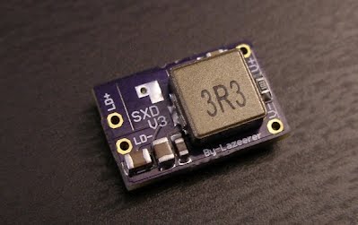
Super X-Drive Laser Driver
Regular price $30.00 USDRegular priceUnit price / per